
Lab 6
Prelab
My setup for handling data over Bluetooth was similar to what I did in the previous lab. I used my commands to change Kp, Ki, and Kd over bluetooth, which is shown again below.
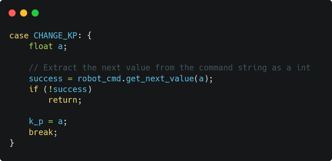
At a high level, to send data over bluetooth, I first connect my Artemis over Bluetooth. Then, from my laptop, I start the notification handler and send my PID_CTRL_ANGLE command (described in further sections). On the Arduino side, my ble.h file is used from the ble_arduino.ino file as it contains the handle_commands() function which describes what the PID_CTRL_ANGLE command does. This specific command not only calculates the necessary PWM signal to send to the motor drivers, but also stores time-stamped data of the angles and PWM signal (among other data), which is sent back to my laptop over bluetooth after the data is done being collected.
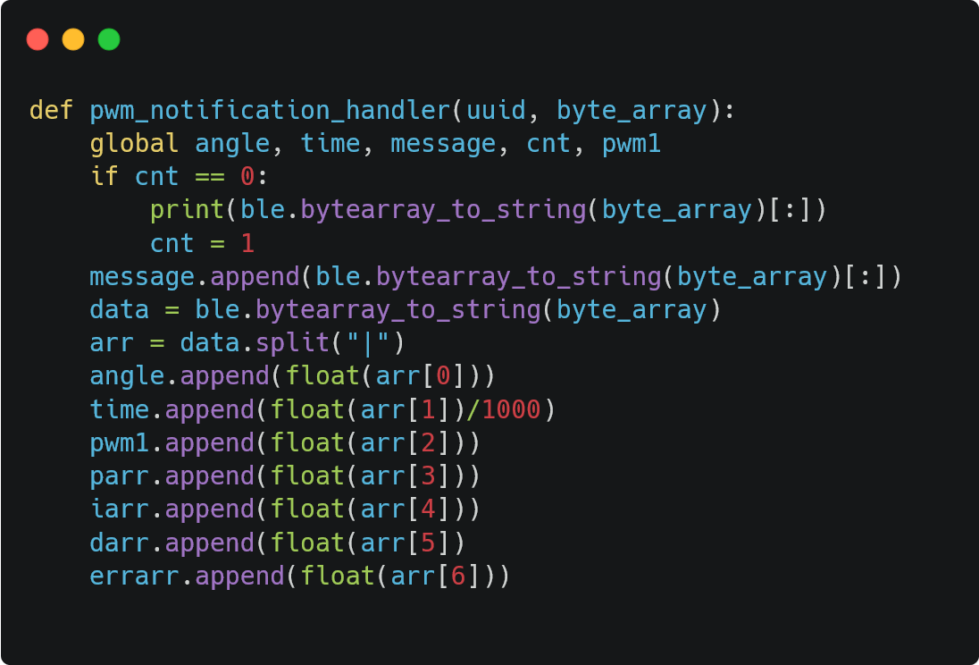
My notification handler on my laptop's side is shown below:
PID Input Signal
Integrating Gyroscope Data
If we integrate a gyroscope to get an estimate for the orientation of the robot, there can be increased error. This is because gyroscope has inherent drift due to its circuits and integrating the bias can result in more error. This time-varying bias can make it difficult to measure a robot's orientation, as the angle measured by the gyroscope may not be the same even if the robot is stable. In the short term or if the bias is constant, this error can be approximated as linear, but as time goes on or if the bias is noisy/non-linear, it can look more quadratic or randomly increasing.
Resolving Bias
In order to minimize or fix these problems pertaining to bias, it is possible to calculate how the gyroscope is biased through determining a trend in the data and calibrating the gyroscope using this data. Another way of reducing bias is to use the Digital Motion Processor (DMP), which essentially combines readings from the accelerometer, gyroscope, and magnetometer to fix the bias.
The gyroscope itself has a maximum rotational velocity reading of +/- 250 degrees per second (dps), which can be configured to be higher (up to 2000dps) according to the datasheet but that is what is set in the Arduino library. This is decent for our applications, although it does mean that the robot cannot do a complete 360 degree turn without additionally logic. Again, I ended up using DMP so I didn't have to worry much about gyroscope configurations.
Derivative Term
In theory, it makes sense to take the derivative of a signal that is the integral of another signal. However, if there is noise in the system, it can be amplified when taking the derivative. Changing the setpoint while the robot is running will result in a significant derivative kick. Therefore, we need to be careful when taking the derivative, and having a lowpass filter before the derivative term can decrease the noise in the system.
Programming Implementation
PID Discussion
In this lab, I was able to implement a PI controller to control the orientation of my car. I chose a PI controller as adding a Proportional component improves response time, and having the Integral component decreases steady-state error.
Code Details
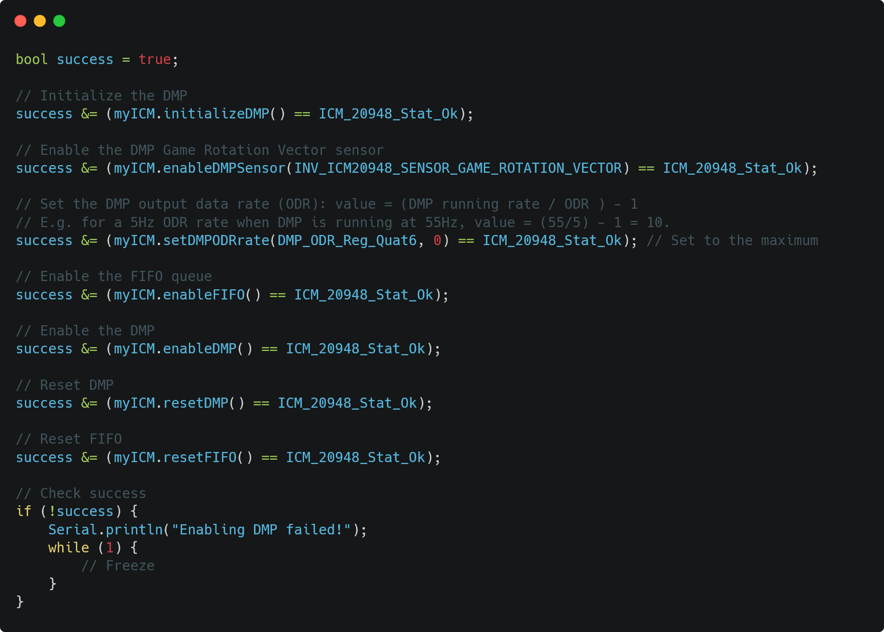
First, I set up my DMP in my setup() function, as shown in Figure 1 below. This piece of code initializes, enables, and resets the DMP, enables the rotational sensor, sets the rate to record data, enables and resets the FIFO queue which records data, and lastly makes sure that all of these tasks were completed successfully.
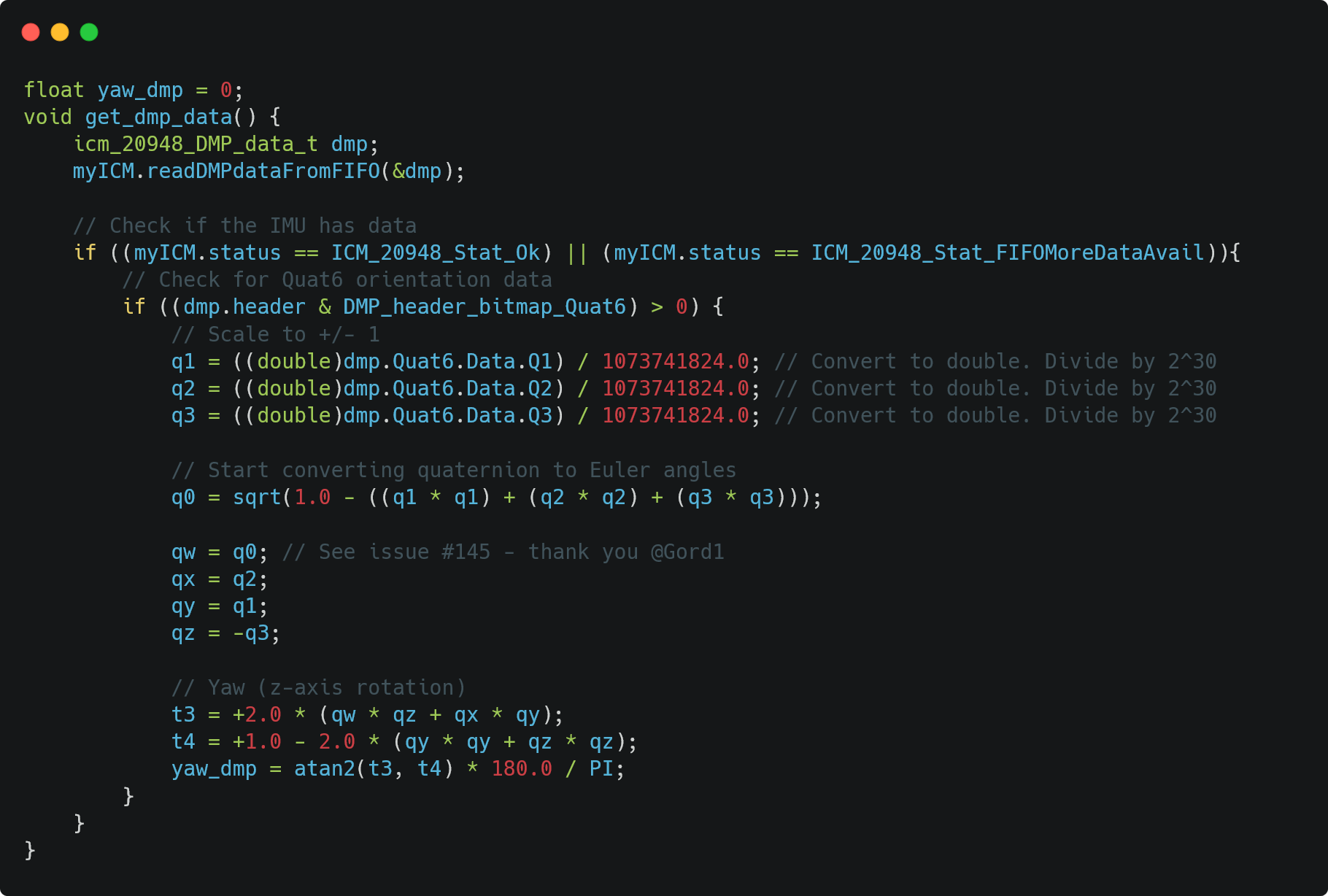
In order to collect data using the DMP, I created a function called get_dmp_data(), which reads orientation quaternions (another kind of number system) in the three directions and calculates the yaw accordingly. The code is shown in Figure 2 below.
After this initial set up to run DMP, I was able to find my robot's orientation through accessing a global variable, yaw_dmp. My command to calculate PID is shown in Figure 3 below:
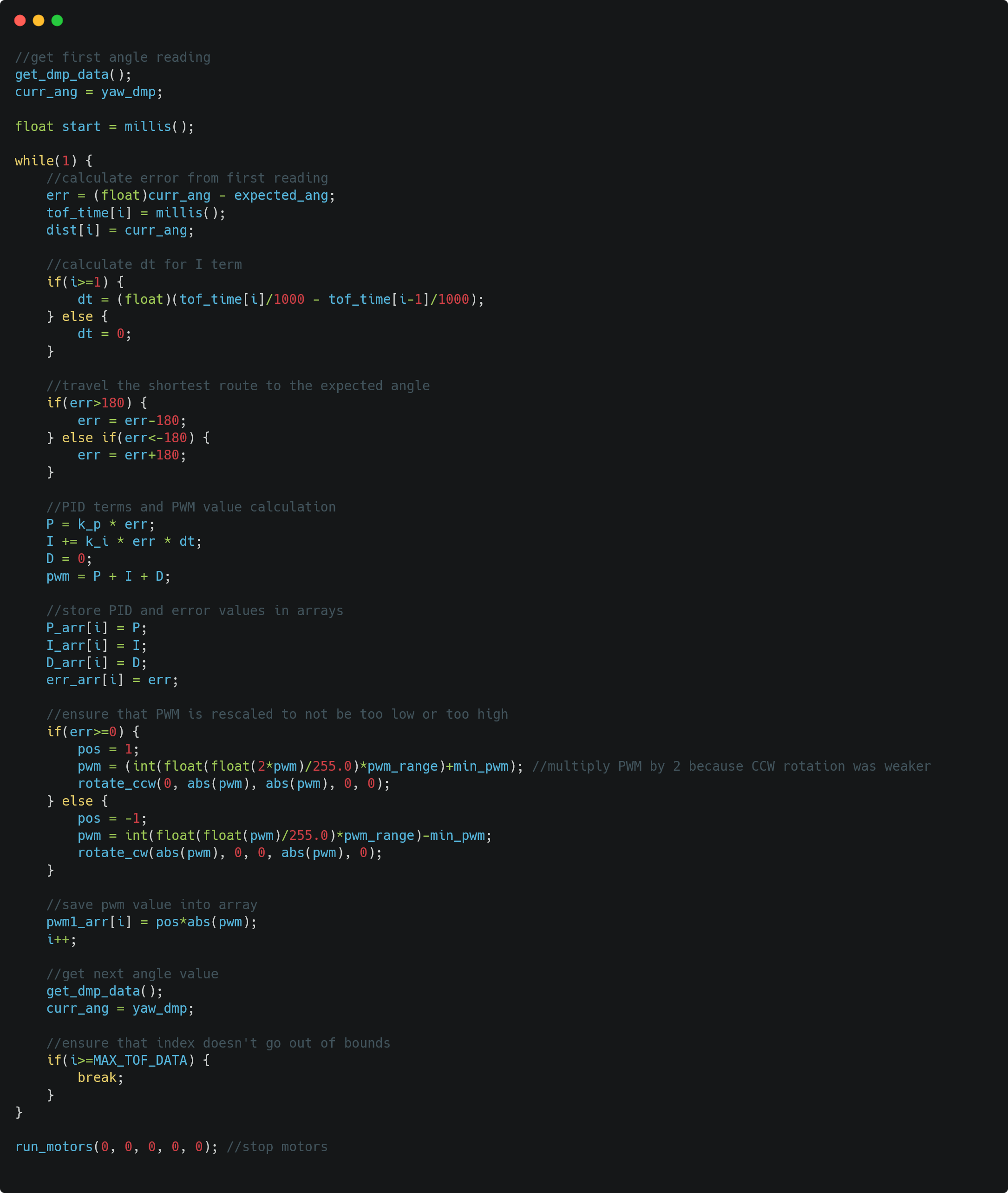
There are a few design decisions to note here. First, in Lab 5, I coded my PWM values such that if they are lower than a certain threshold, I would set them to the minimum PWM value needed for the motors to run. I thought that doing so would not represent the scale of PWM well, so in this lab, I rescaled my PWM signals to be outside of the deadband. This can be seen in my demo graphs in the next section. Second, I had to use a constant multiplication factor of 2 when rotating counter-clockwise, as I noticed that my wheels were unable to generate enough force in this direction.
Parameter Tuning
The vast majority of this lab was spent working on parameter tuning. I started with setting my Kp to be at 0.07, as that is what my Kp was in the previous lab. In this lab, however, I found that in order for the system to settle to a desired angle quickly, I had to increase the Kp to be around 0.4-0.5; demos of both Kp=0.4 and Kp = 0.5 are shown in the next section.
In this lab, I also had to tune my Ki parameter, as I implmented a PI controller. In order to do so, I started with a value of 0.1, which proved to be too high as my robot oscillated a lot. Then, I kept on decreasing my Ki until I found an optimal value of around 0.01.
Code Formatting
I have implemented my code such that I can change the parameter values without having to re-flash my code again. Due to this, for future applications, I should be able to update the setpoint in real time. Currently, I have not set up the functionality change the orientation as the robot is moving, but I will add that soon.
Range/Sampling Time Discussion
Using the same method as Lab 5, I calculated the frequency at which DMP was returning values, as shown below.
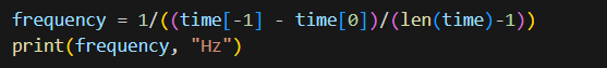
I received a frequency of 52.33Hz for the DMP and a loop frequency of 56.21Hz, which means that the loop is able to keep up with the speed of the DMP.
Demos
I have attached videos and graphs for three sets of working orientation control below!
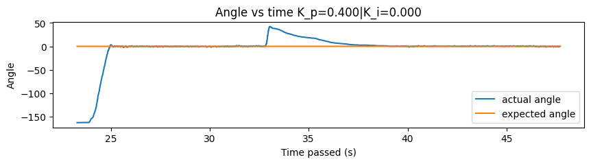
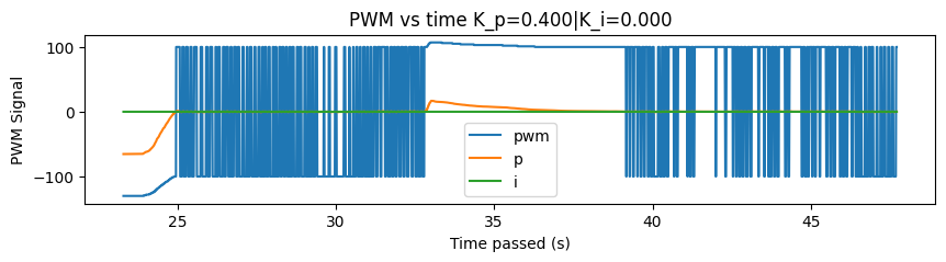
Kp = 0.4 and Ki = 0
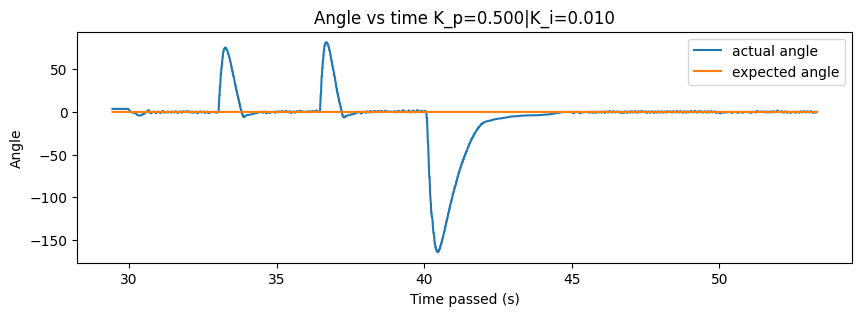
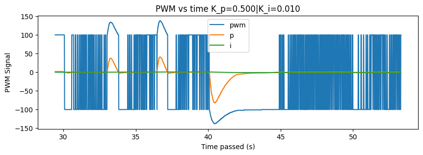
Kp = 0.5 and Ki = 0.01 (Attempt 1)
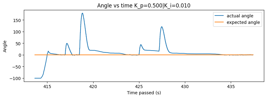
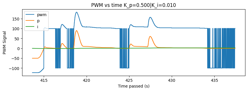
Kp = 0.5 and Ki = 0.01 (Attempt 2)
References
- DMP Tutorial: https://fastrobotscornell.github.io/FastRobots-2025/tutorials/dmp.html