
Lab 5
Prelab
In order to allow for easier programming of the Artemis Nano while debugging the PID control, I performed a few steps. First, I split my ble_arduino.ino file into multiple header files for improved readability. I first added a ble.h header file, which consisted of the handle_command() function, which was the largest function in this program, along with a few other helper functions. I also added defines.h, which contains all of the global variables, and cmd_types.h, which contains the CommandTypes enum.
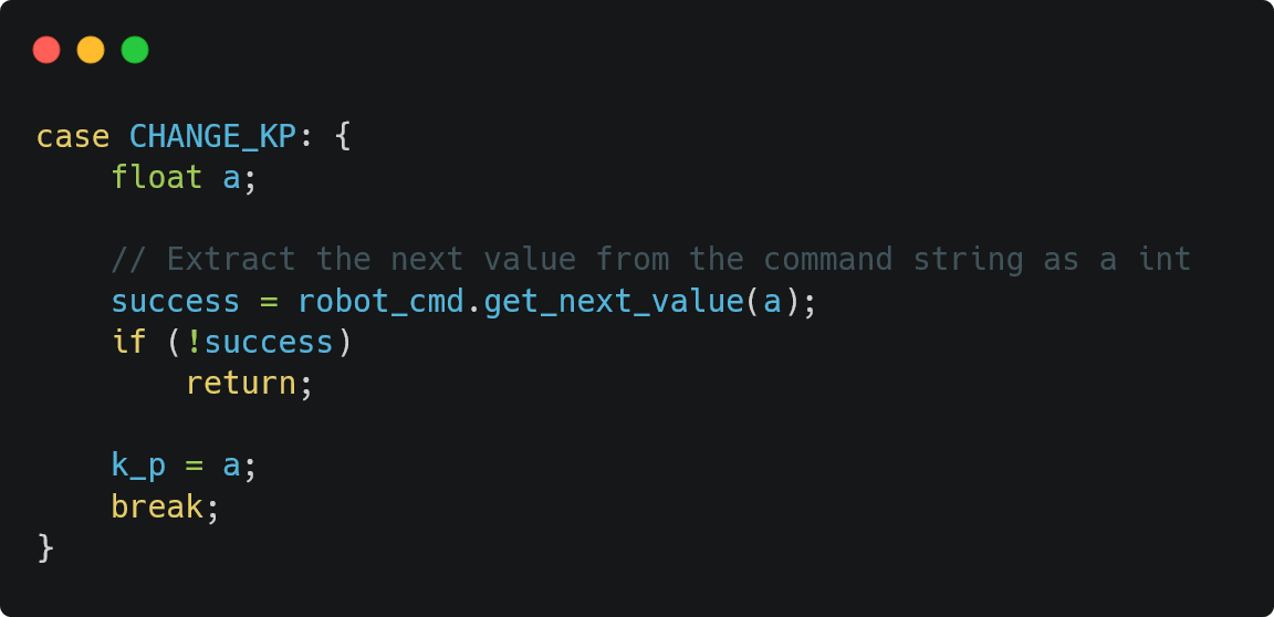
Furthermore, I added more commands to allow me to change the PID parameters, Kp, Ki, and Kd. Figure 2 shows the command for changing Kp.
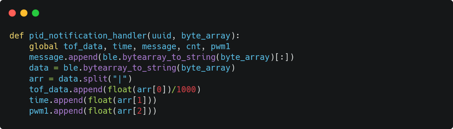
Next, I implemented a notification handler on my laptop, which would allow my data to be stored properly into arrays. which could then be plotted.
I also added a hard stop after 10 seconds and another in the case that the bluetooth was ever disconnected.
At a high level, to send data over bluetooth, I first connect my Artemis over Bluetooth. Then, from my laptop, I start the notification handler and send my PID Control command (described in further sections). On the Arduino side, my ble.h file is used from the ble_arduino.ino file as it contains the handle_commands() function which describes what the PID control command does. This specific command not only determines the necessary PWM signal to send to the motor drivers, but also stores time-stamped data of the ToF sensor and PWM signal, which is sent back to my laptop over bluetooth after the data is done being collected.
P Control
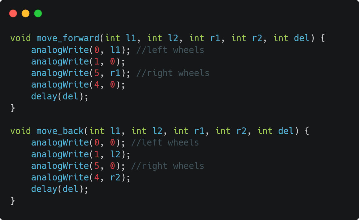
General Code
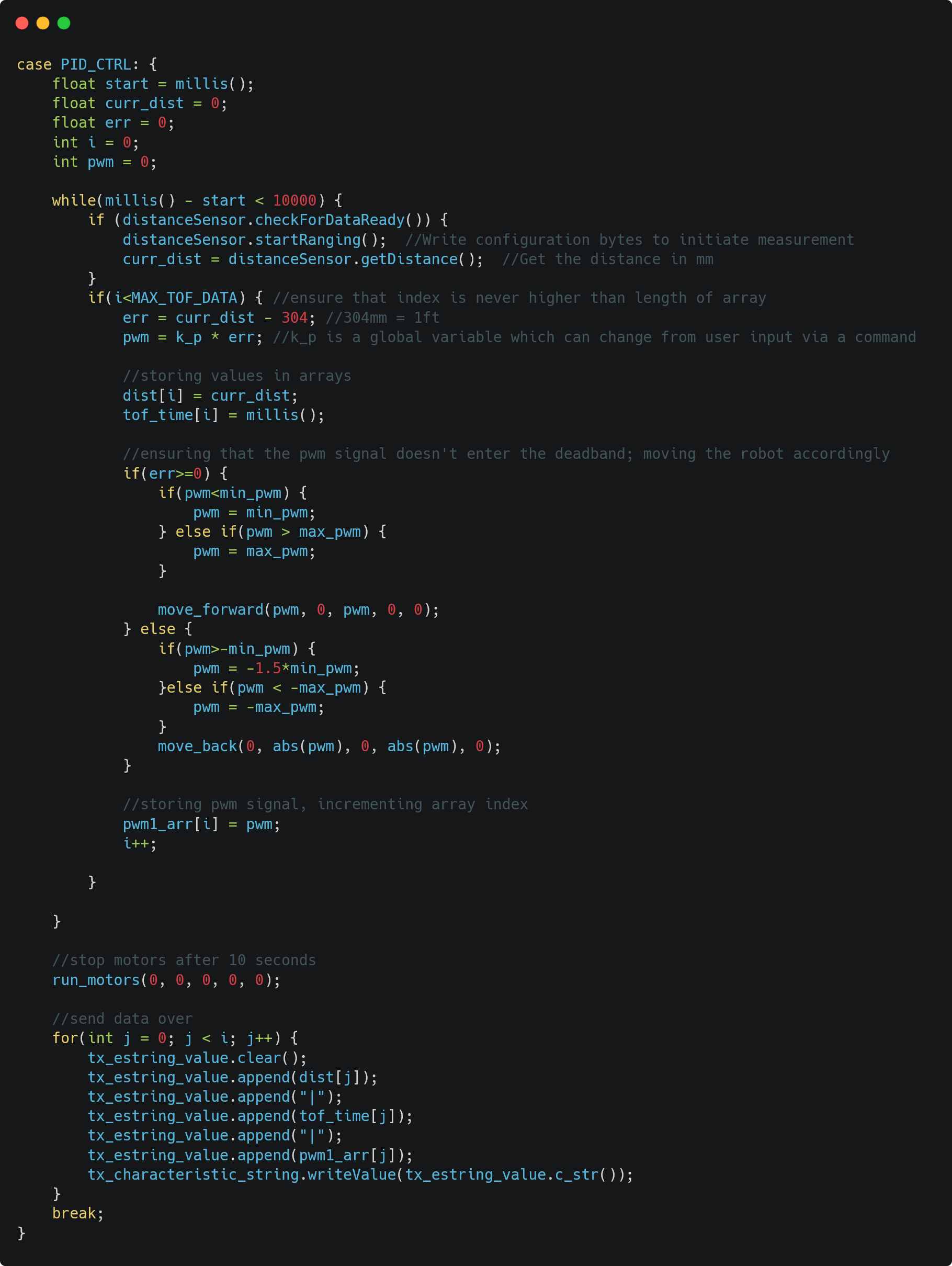
distanceSensor.clearInterrupt();
									distanceSensor.stopRanging();
Figure 4 above shows my code for implementing a P controller, which was the first step I took in this lab after setting up my files. This code starts by initializing most variables to zero and recording the start time. Next, I set up a while loop which executes for 10 seconds, as I anticipated that my robot will be able to reach a steady location within this time. Inside the while loop, I first collect the data from the ToF sensor if it is available. Then, I calculate the error which is used in the p-term (k_p * error) of my controller, which currently is the only term that determines the PWM signal. I ensure that the PWM signal doesn't enter the deadband region, in which the PWM signal is too slow to make the wheels move; I also use the helper functions to use the PWM values to move the motor. Then, I store PWM, ToF, and time values in three separate arrays, ensuring that I don't go out of the arrays' bounds. After the 10 seconds, all of the collected data is transmitted.
From the previous labs, I kept my range to be the lowest possible, as I found that even the lowest range could support around 3m worth of distance relatively accurately. Furthermore, due to this lower range, I was able to increase the sampling frequency of my ToF sensor.
Parameter Tuning
This lab took especially for me, as my initial while loop set up was incorrect. When I started working on this system, my while loop stated that it would stop executing when the ToF sensor recorded a distance of 304mm. Although this achieved the purpose of stopping at the 1ft mark, this was incorrect as we wanted to see how the robot is able to adjust itself to be exactly 1ft away from a wall. Also, it was possible that the ToF sensor never records an exact measurement of 304mm due to the speed of the robot. Therefore, by stopping when we record a distance of 304mm, I was unable to see the robot's control and the robot could run infinitely.
After identifying this main issue, along with fixing my placement of helper functions and global variables, I was able to focus on tuning my parameters.
I started with setting my Kp to be at 1, as I though that would be a reasonably low value. However, when I did so, the robot's PWM value shot up to be the maximum possible number, and the robot crashed into the wall. Note that I initially set my robot's maximum PWM to be 100, as I didn't want the robot to go too fast. My deadband was set to be from -40 to 40 (PWM values).
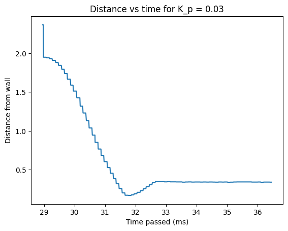
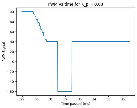
Below is a demo of my P control working as intended.
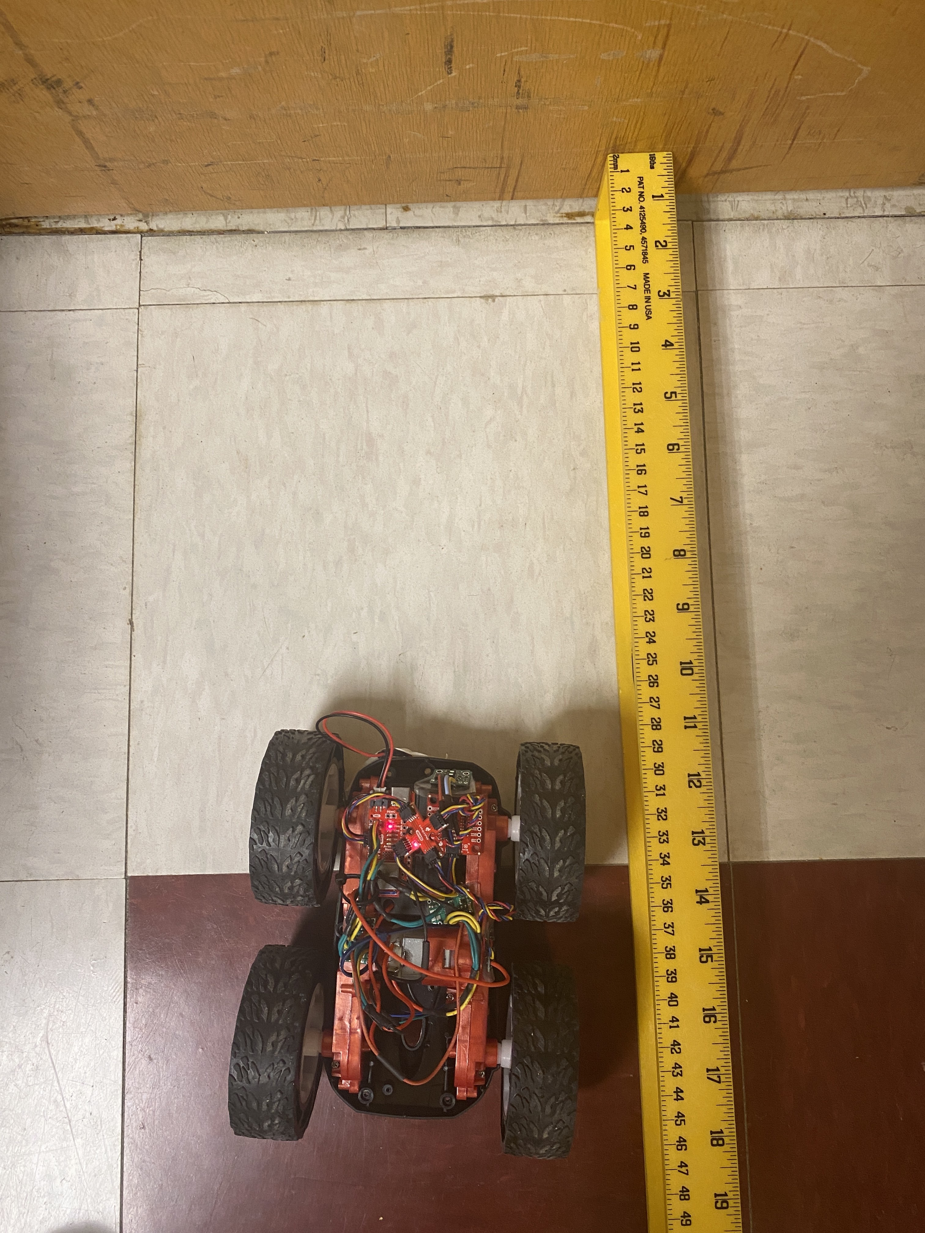
To ensure that my robot was stablizing at the right distance I used a ruler to measure the distance, as shown below.
I also had a considerable amount of difficulty with my ToF sensor, specifically the one on the front. At times, the readings from it did not make much sense, however, my control logic started working as soon as the ToF resulted in good values. I soldered my weaker wires on the ToF sensor again and even heat shrinked thicker wires onto the QUIIC connects and the ToF sensor, but I still feel that my ToF sensor doesn't work properly at times. Figure 6 and the video below shows a case where my ToF sensor wasn't collecting data well initially, but then started working again.
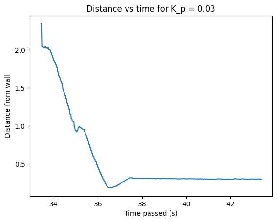
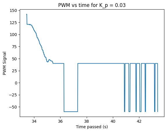
After testing on bare floor (and a partially charged battery), I found that a Kp of 0.03 was suitable for this experiment. When I tested my robot on a carpet, the Kp had to be increased to around 0.08 due to the increased friction.
Speed!
After I was certain that my P control was working properly, I increased the maximum PWM to be around 220 to allow the robot to go as fast as possible when necessary; going above this threshold of 220 resulted in unexepcted behavior at times with my robot such as the wheels turning backwards. Below is the video and figure showing the max speed, which achieves steady state in around 4 seconds.
Potential Improvements
Due to the intricacies described above along with certain bugs in my setup, getting my P controller to work took my quite a bit of time. If I were given more time, I would definitely add an I-term into this controller, as it would allow the system to decrease steady-state error therefore improving stability. I could also explore setting a timing budget and lowering the integration time, both of which have tradeoffs with accuracy and speed and would require further analysis.
Extrapolation
Frequency of ToF Sensor
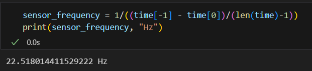
The frequency of the ToF sensor is around 22Hz, which was calculated as shown below. Here, the code to store data into the arrays was placed inside the if statement which checks for the ToF data.
PID Control Loop Speed
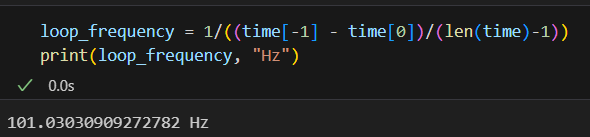
The loop frequency is around 101Hz, which was calculated using the metric below. Here, the code to store data into the arrays was placed outside of the if statement which checks for the ToF data.
Extrapolation Implementation and Demo
From finding the frequency at which the sensor collects data and that the loop executes, we can see that the ToF sensor collects data at a much slower rate than the PID loop. In this case, extrapolation can be used to predict future measurements using past data, which can reduce the number of oscillations that my robot does.
In order to implmenent a simple linear extrapolation algorithm, I collected two data points for the time and the distance before the current time and distance. We can use these two points to calculate a future distance, which is predicted using a linear relationship by using the point-slope formula: y = m(x - x₁) + y₁. Here m = slope = (y2 - y1) / (x2 - x1). In terms of code, the figure below shows the additions to our PID command.
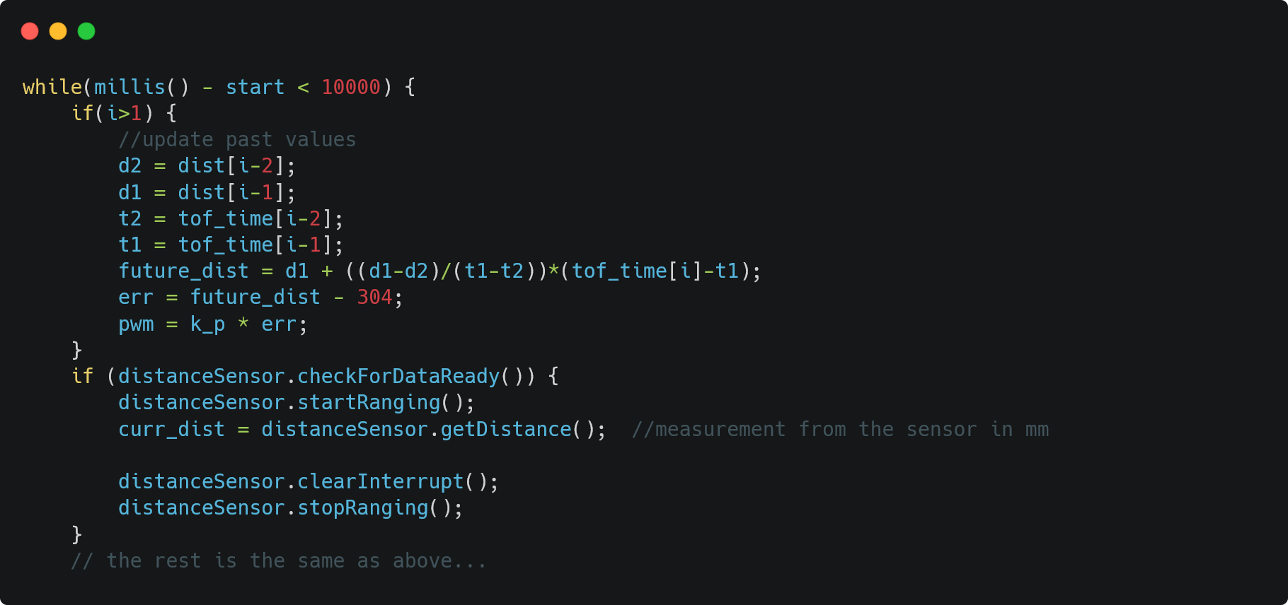
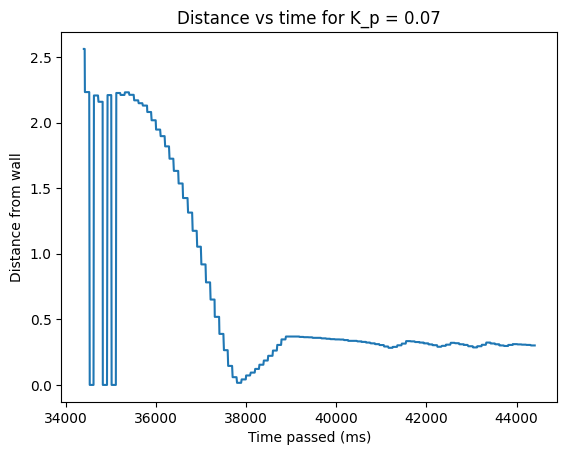
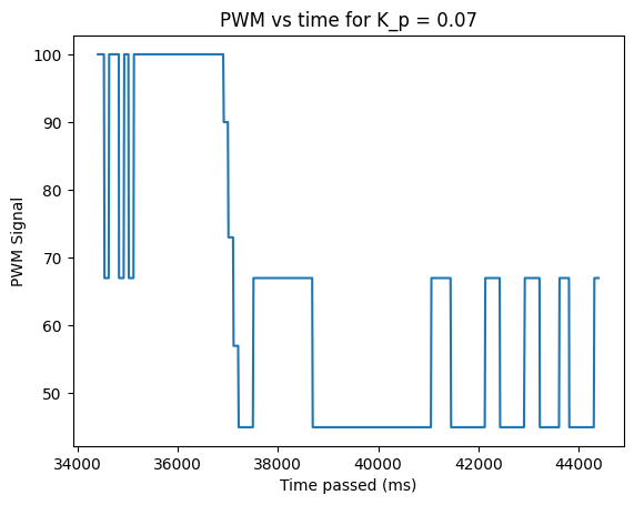
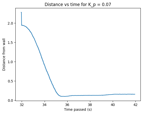
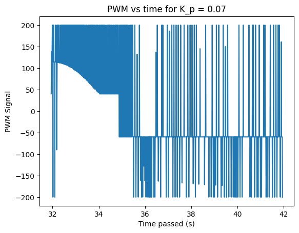
Below is a demo of extrapolation working on my robot, along with the necessary graphs. We see that adding extrapolation introduced a lower amount of oscillations along with smoother distance changes, although the PWM values vary quite a bit. Note that I increased the Kp value to be 0.07 as the ground now has a carpet.
References
- I refered to Nila Narayan's webpage to help debug some of my code.
- Code snippet creation: Carbon