
Lab 3
Prelab
I2C Sensor Address
From the Time of Flight (ToF) sensor datasheet, the sensor's I2C address is supposed to be 0x52.
Using 2 ToF Sensors
Since we want the car to have two ToF sensors, we will have to change the I2C address of one of them. I chose to do so by connecting the XSHUT pin to the Artemis board and then turning the SHUTDOWN pin on and off to change the address of the other sensor.
In order to use the ToF sensors best, I will add one sensor to the front of the car and one on the side of the car. This will allow the car to detect obstacles in front of it and beside it which can ensure that the car doesn't hit anything in those directions. The car will be unable to detect obstacles behind it, however, we can assume that there is nothing trying to hit the car and that the car will only move forwards.In the case we have to go backwards, we can rotate and move forwards.
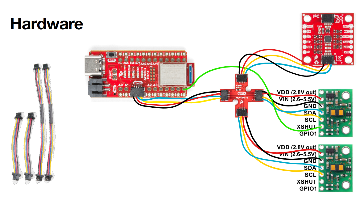
Wiring diagram
Figure 0 shows how I planned to wire my components together.
Lab Tasks
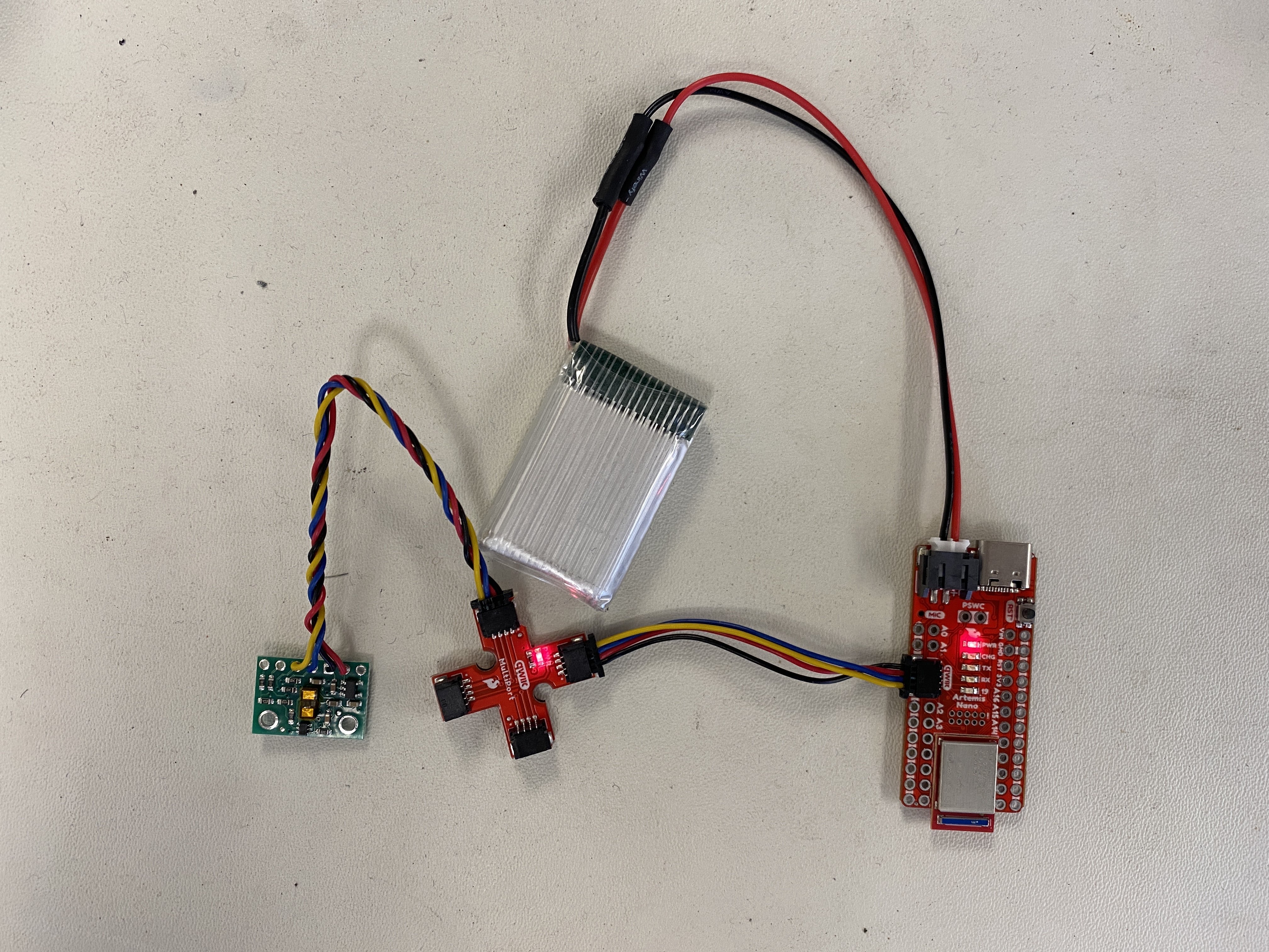
Here is the Artemis connected to the QUIIC breakout board, which is connected to a Time of Flight (ToF) sensor.
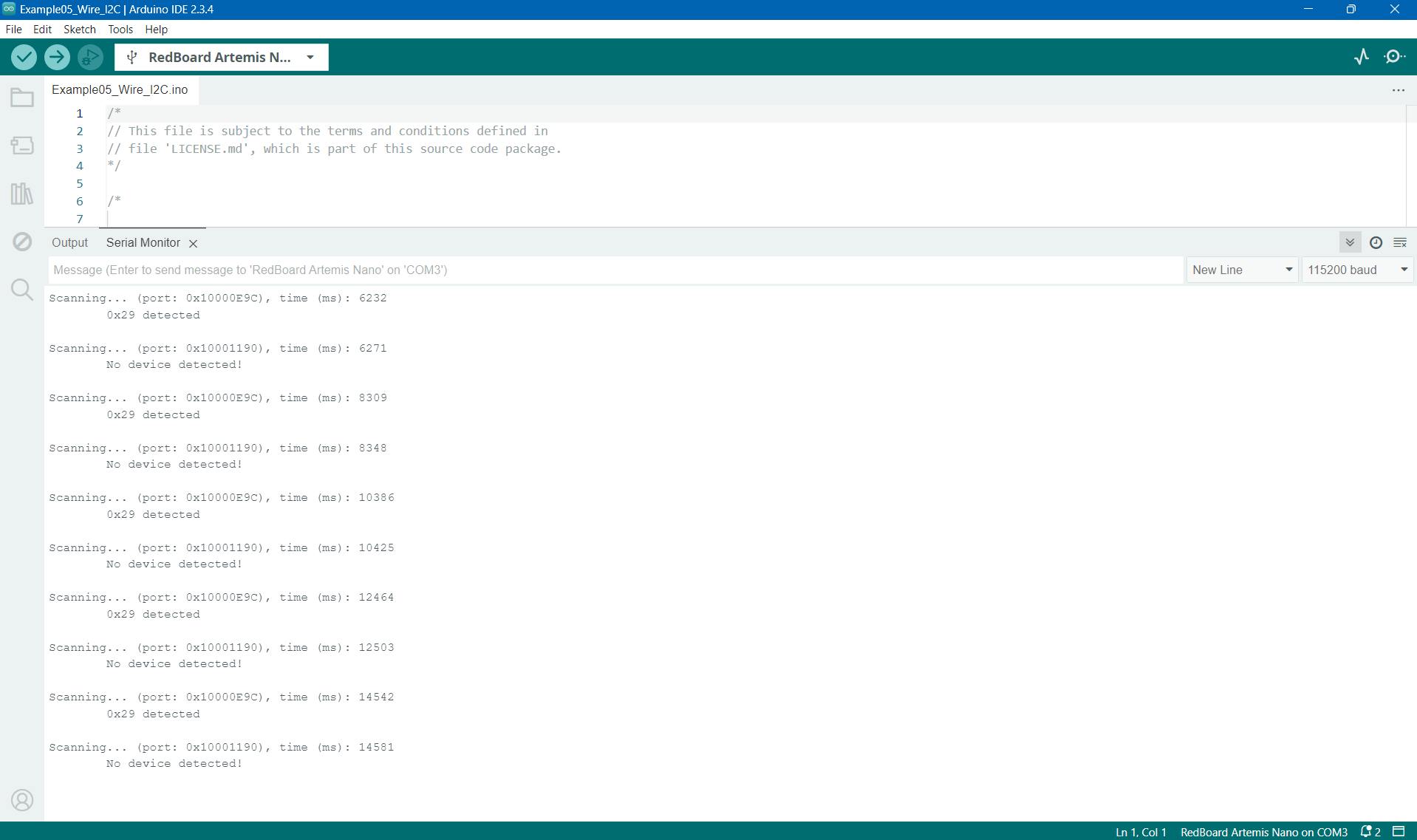
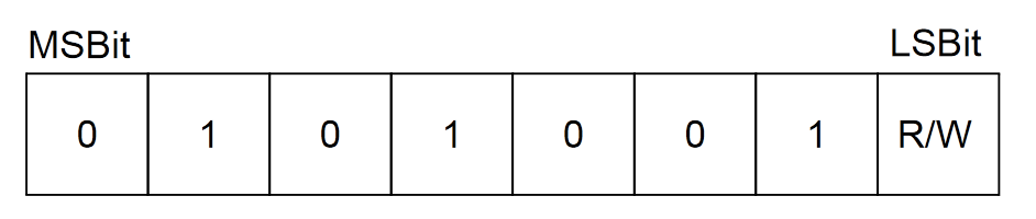
We expect the address to be 0x52, but we see that the address is 0x29, thus the address does not match what we expect. This is because, as the datasheet specifies, the last bit is a read/write bit and is 0 since we are reading. Therefore, if we add a 0 to the LSB (equivalent to a left shift) of the 0x29 address, we get 0x52, as expected from the datasheet. Below is a figure from the datasheet which describes how the bits are allocated.
ToF Modes
| Mode | Pros | Cons |
|---|---|---|
| Short |
|
|
| Medium |
|
|
| Long |
|
|
Testing Chosen ToF Mode
I chose the Short ToF mode, since we will need to perform quick computations moving forwards, and the short mode has the highest sampling rate of 50Hz. I then conducted an experiment to measure the distance between the ToF sensor and a white box. This measured distance was compared to the actual distance between the sensor and the box through a tape measure. This experimental setup is shown in Figure 4 below.
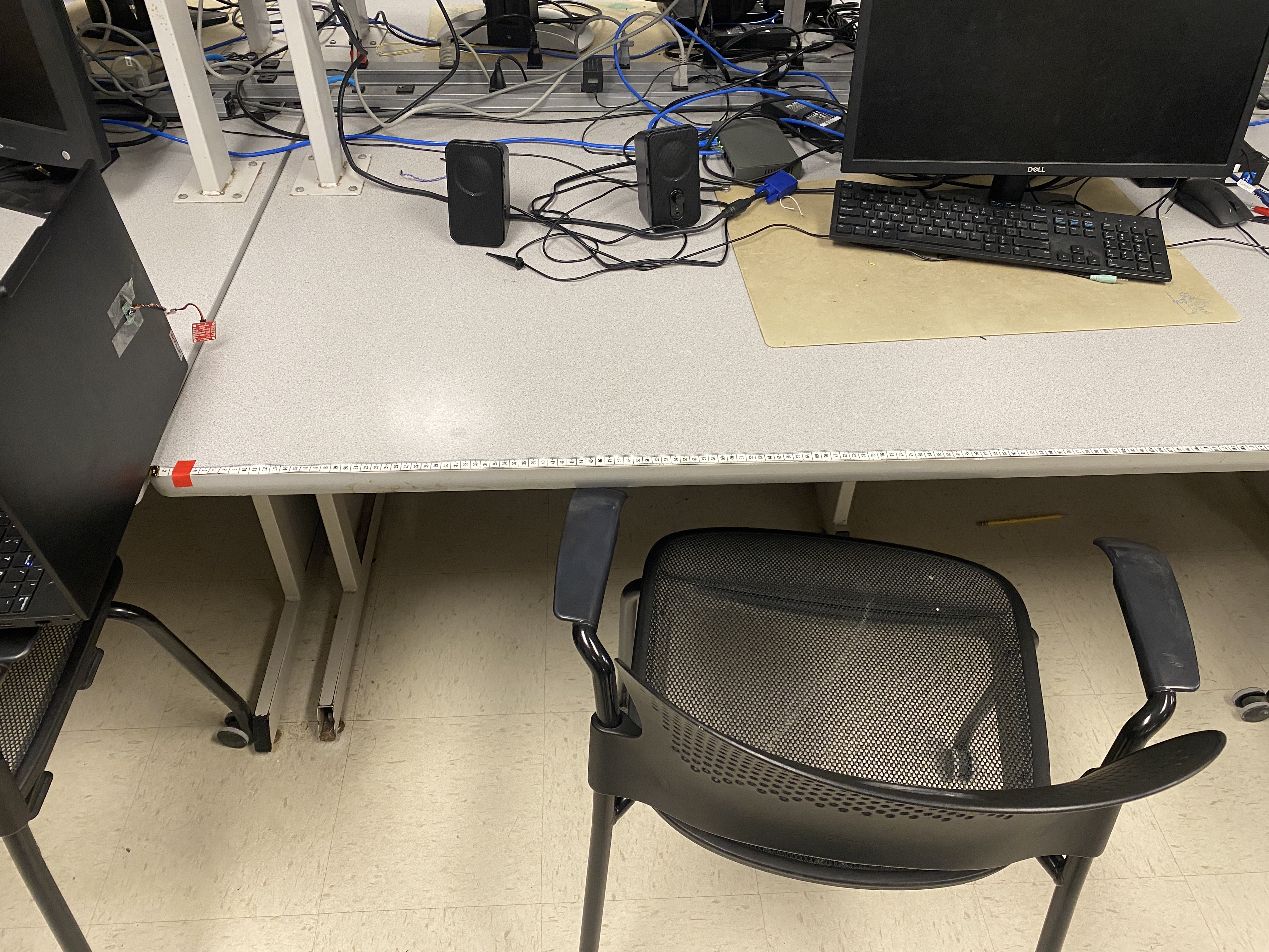
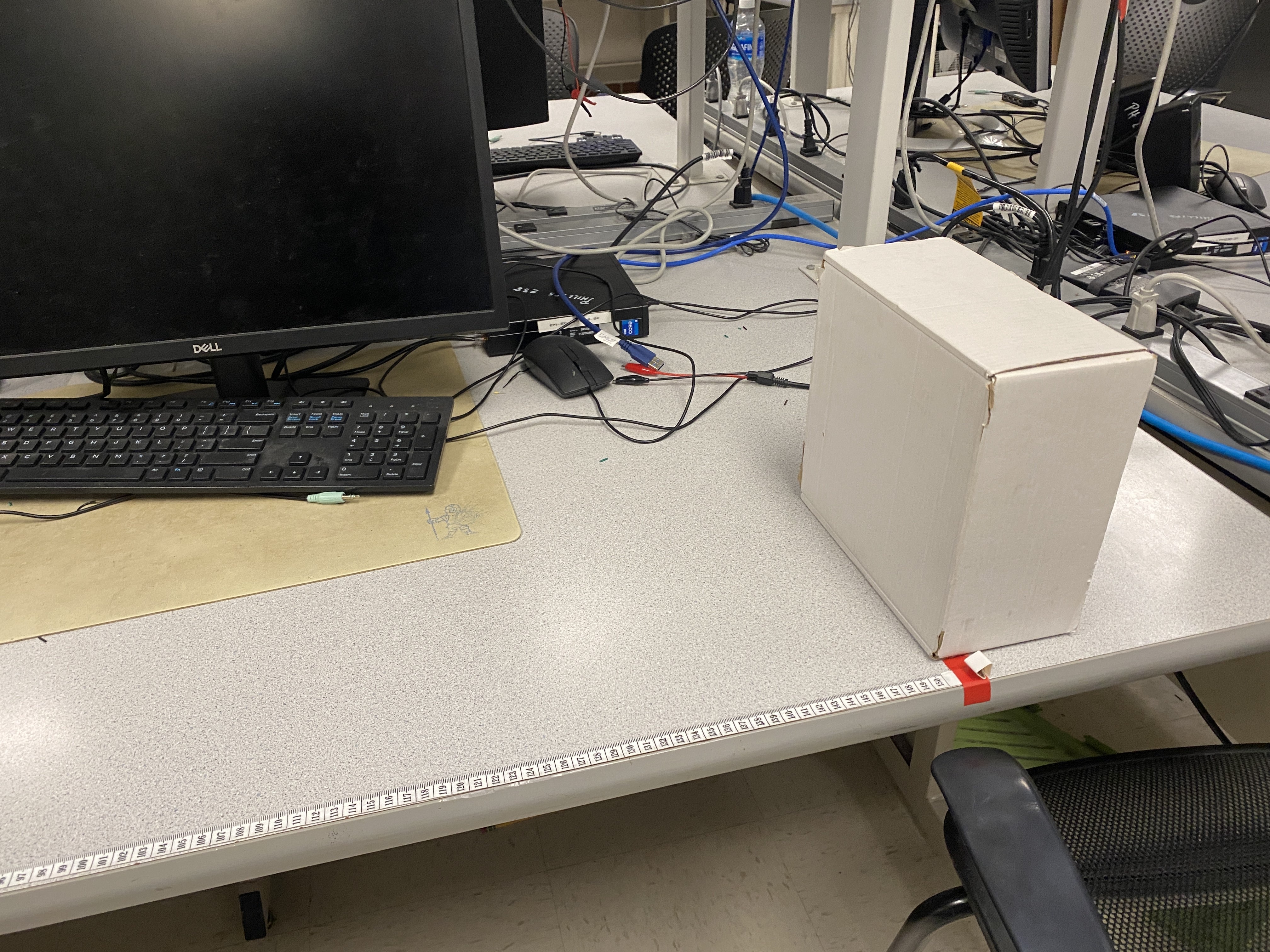
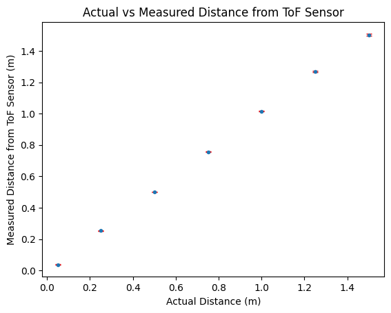
Figure 5 below shows the results from the experiment. Each point consists of averages and standard deviations of 100 values from the sensor. Overall, as the distance of the box from the sensor increased, the absolute difference (|a-b|) between the measured and the actual distances increased. This absolute difference between the values ranged from 0.001m to 0.02m (at the worst case), which implies that the sensor was quite accurate. Furthermore, the standard deviation of the measured data was the highest when the box was placed 1.5m away, which makes sense since this was past the specified range of the short measurement mode. The sensor was quite precise (standard deviation of less than 0.01m) for distances less than 2 meters. Furthermore, the results were reproducable, as I received similar results when re-running the experiment multiple times.
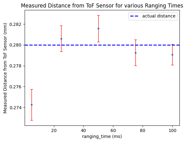
As part of this experiment, I also varied the ranging time from 5ms to 100ms using the setTimingBudgetInMs() function. I set my sensor 28cm away from a white box and measured ToF data for different ranging times. The results are shown in Figure 5A below. Overall, the accuracy was best around a ranging time of 25ms, although the data was most precise for 100ms. The ranging time of 25ms was the second best in terms of preciseness, so this value should be preferred.
Connecting Two ToF Sensors
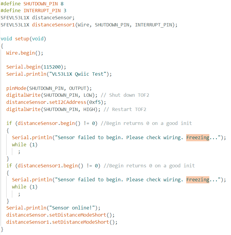
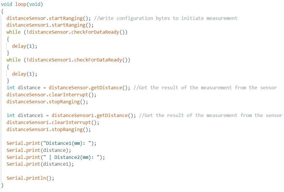
Next, I added to the ReadDistance Example to incorporate another ToF sensor. There were a few steps that I took to configure this properly. First, I soldered a wire from GPIO8 on the Artemis Nano to one ToF sensor's XSHUT pin. Then, on the software side, I added another SFEVL53L1X sensor configured for a SHUTDOWN_PIN of 8 and an INTERRUPT_PIN of 3. I set the SHUTDOWN_PIN as an output, and changed the I2C address of the initial ToF sensor to be 0xf5. In doing so, I had to turn of the second ToF sensor. In order to collect the data, I called the startRanging function, ensured that the data was ready, got the distance, and then cleared the interrupt & stopped ranging. The setup and looping code is shown in Figure 6 below.
The video below shows the data collected from the two ToF sensors using the code above.
Improving ToF Sensor Speed
In order to improve the speed of the code execution, I made a few improvements to the code. First, I decreased the number of characters being printed to the console since that can cause delays. Next, I only printed a data value when it was ready, through first checking if the data was ready through distanceSensor.checkForDataReady(), then getting the distance and printing it. This was done for both sensors, and the code is shown in Figure 7.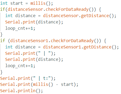
To find the speed of execution, I placed the code in Figure 7 in a while loop which executed for 5 seconds. In those five seconds, there were a total of 2052 ToF values collected including both sensors. Thus, each ToF sensor gets around 205 values per second. The delay to compute and print the values was also calculated in the code above, and the average delay was 5ms. Thus, the code was able to loop through the sensor data faster than the sensor was able to produce the data. Therefore, the limiting factor is the ToF sensor.
Adding Bluetooth Support
I added functionality to the ble_arduino file to support transferring data from two ToF sensors and an IMU through bluetooth. On the python side which ran on my laptop, I set up a notification handler to collect data that was received through bluetooth, which is shown in Figure 8 below.
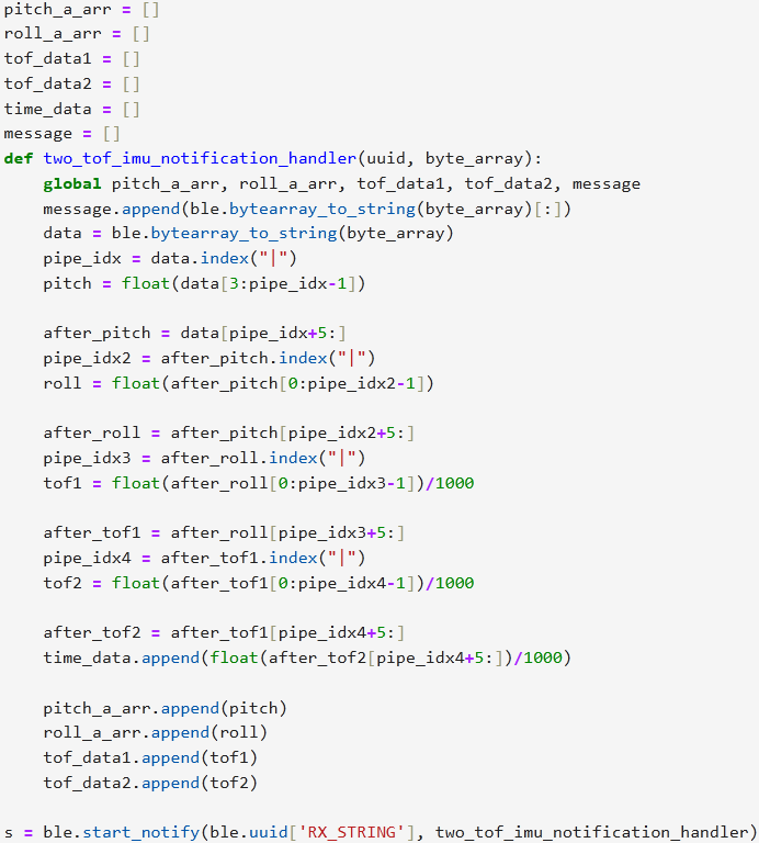
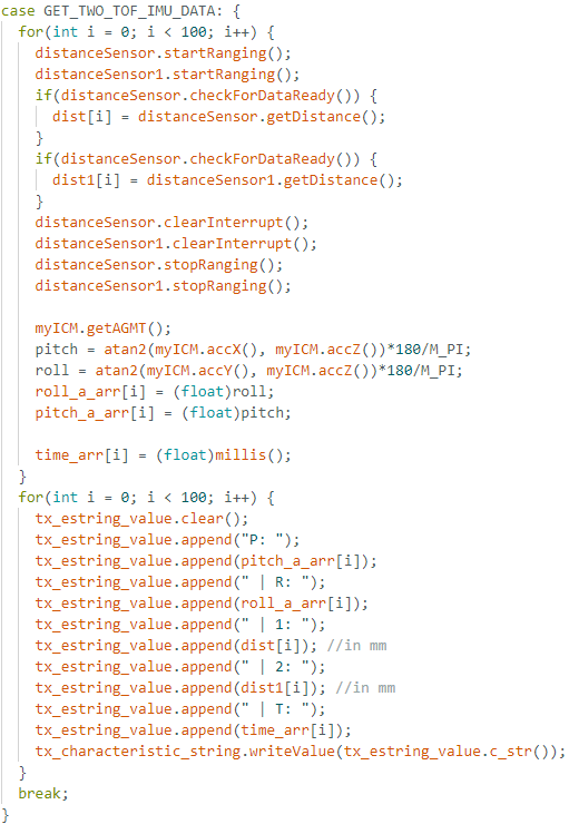
On the Arduino side, I added a command, GET_TWO_TOF_IMU_DATA, which received data from all sensors (as done in the steps above and in previous labs) and stored them into an array. After the array was filled, the data was sent over through bluetooth. Figure 8 shows the command implemented.
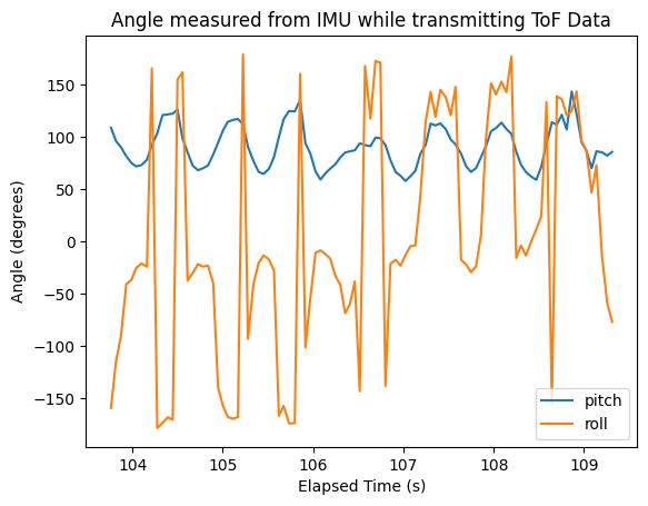
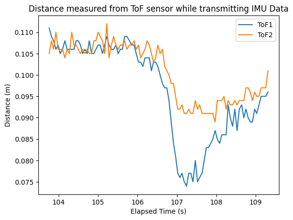
Through implementing the code above, I was able to record data (received via bluetooth) about the angle recorded my IMU as I moved it and the distance between my ToF sensors and a yellow box that I placed. Figure 9 shows the results of this experiment.
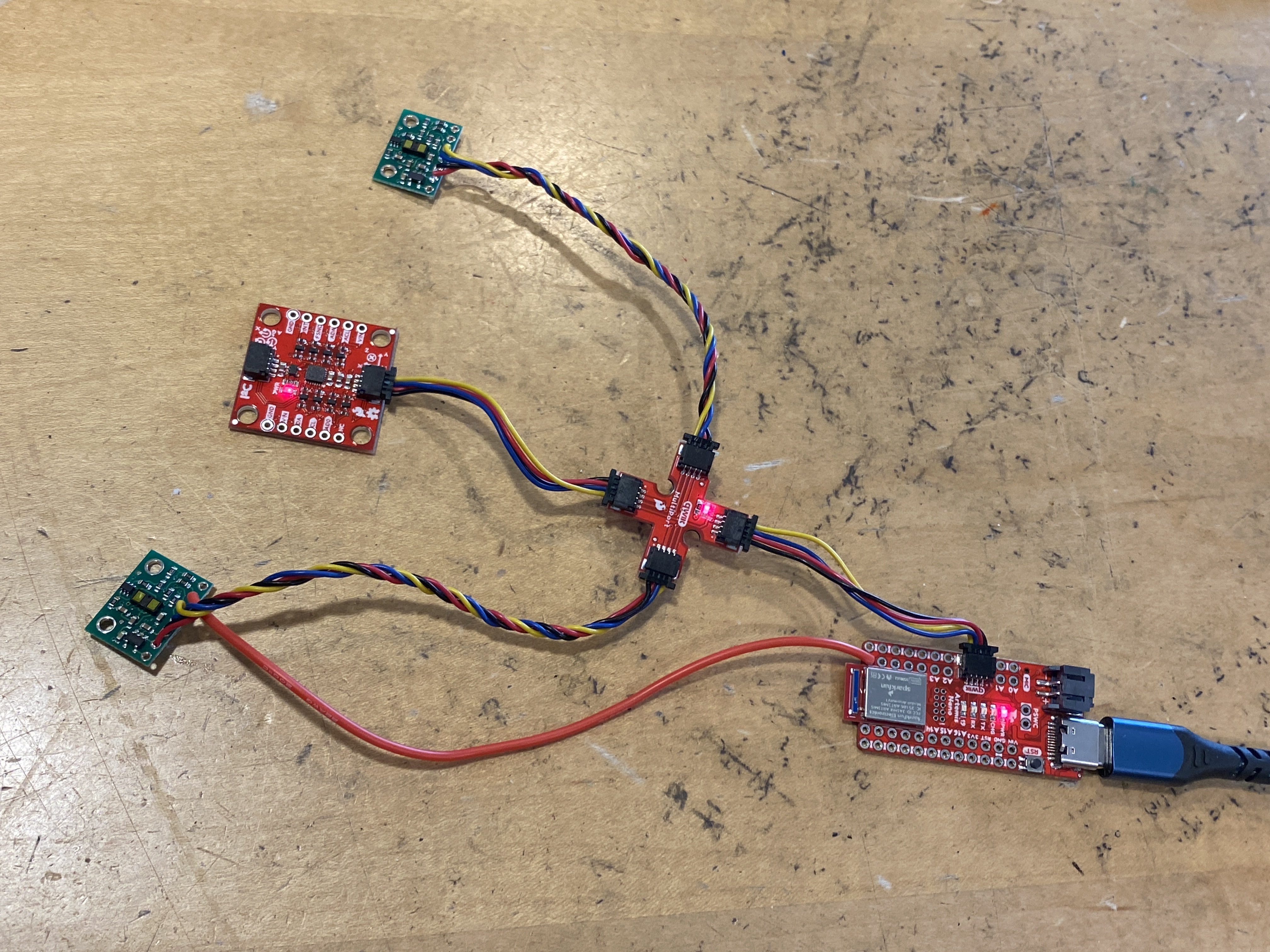
Below is an image of my final hardware setup, consisting of the two ToF sensors and an IMU.
Resources
- For HTML tables: https://www.w3schools.com/html/html_tables.asp
- IMU Details: https://www.pololu.com/product/3415